Trevor Marshall
BiQuad 802.11b Antenna
11dBi, wide band
Trevor MarshallBiQuad 802.11b Antenna11dBi, wide band |
|
***Engadget builds and tests a BiQuad/Primestar combination ***
Miikka Raninen (OH3GPJ) builds and tests the biquad
Click here for details of Mark LaPierre's 1100ft link through forest canopy, and comparison with Pringles can performance.
Click here to link to Koen Weijand's page on using an 18inch dish and feed details
Link to my tutorial 'Antennas Enhance WLAN Security' from BYTE.com, October, 2001
Click here to read about the High Gain (15-17dBi) Slotted Waveguide WLAN antennas
|
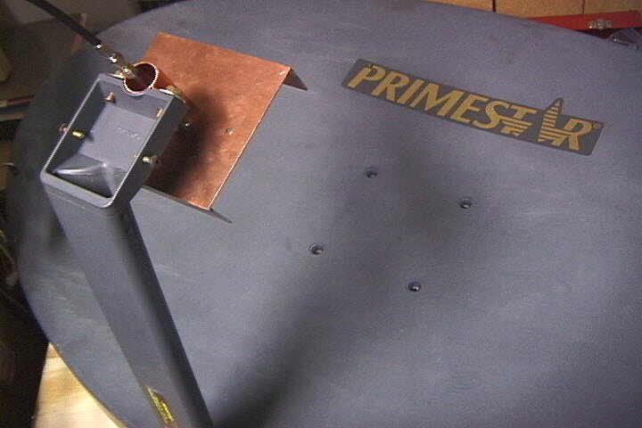
Low sidelobe 802.11b BiQuad feed for Primestar dish The Primestar dishes are high gain, low cost, parabolic reflectors with an offset feed. They have superior sidelobe performance when compared with a wire grid antenna, reducing the chance that somebody off of the axis of your link will be able to interefere with it. But they are hard to feed because the f/d ratio varies from about 0.5 in the vertical axis to 0.8 on the horizontal axis. Additionally the spacing between the feed 'slot' and the feed mounting bar is small (about 55 mm), which is less than a half wavelength at 2.4GHz Failure to couple efficiently to the dish's wide aperture, or to minimize radiation into the mounting bar, will result in poor gain and/or significant sidelobes. The feed is oriented for vertical polarization in this photo. To make it horizontal merely rotate the feed by 90 degrees. You will lose about 3dB of gain when using the horizontal mode, as the biquad's radiation pattern is a better match for the dish's oblong shape when vertical polarization is used. |
 |
|
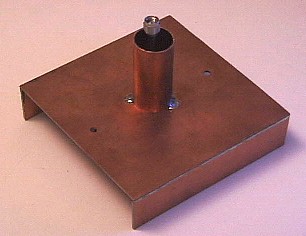
Construction of the Biquad I used Printed Circuit board scraps for the 110 x 110 mm reflector, but it will be just as effective if made out of sheet brass or copper. Aluminum can be used if soldering of the rigid coax is not required at the feed point. The reflector's 'lips' are 30 mm high, and serve to reduce coupling into the mounting bar. Note that they are only required along the main edge axis of the reflector. The lips cut down radiation from the rear lobes of the biquad by about 6 dB The best SWR is obtained when the biquad loop is about 15mm above the ground plane, and the SWR may be adjusted by varying this distance. If you are making a stand-alone antenna, rather than a feed, you will get better gain from a reflector 123 x 123 mm |
 |
|
A piece of 3/4 inch copper piping makes a tight fit with the mount supplied on the Primestar dish The rigid 0.141 diameter coax is soldered to the groundplane to provide physical support for the structure. If the biquad element is constructed carefully there will be no component of radiation along the axis of the coax, no current is induced into the coax outer conductor, and a balun is not needed. An SMA connector can be seen on the end of the rigid coax used to support the biquad element |
 |
|
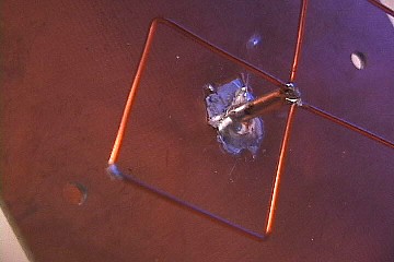
To make the element take a piece of 1.2mm bare or enamelled copper wire exactly 244 mm long. Bend it in half, and then make the bends at the halfway point on each leg (where the solder joints will be). Then bend the 4 remaining right angles so that the element sides are rectangular, and there is about a 1.5mm gap for soldering to the feed. The widths of the two quad elements will be approximately 30.5mm, from wire center to wire center. You may use standard coax cable to connect at this point, if you do not have rigid cable available, but you will have to figure out how to support the loop physically. The best SWR is obtained when the loop is about 15 mm above the ground plane and when the reflector is mounted about 10mm in front of the Primestar's feed bracket. |
 |
Look at NEC2.org for information on simulating the performance of the stand-alone Biquad
BiQuad Antenna for PCS CELLULAR Radio
Need a little bit more range for your cellphone? You can make a Biquad for 1900 MHz exactly the same as the one above, but start with a 304 mm long pice of wire, fold it into 8 arms approximately 39.5 and 38.5 mm long. The ground plane needs to be a little larger, use one about 160 mm (6.2 inches) square. If you don't have a coaxial RF input jack on your cellphone you can couple the signal into its existing antenna using a single quad as a matching stub. It's not perfect, but in practice it works well. Solder an alligator clip to either of the high voltage apex (39mm from the feed) of a single 152 mm loop, and clip that to the antenna stub you are currently using. Now you can put 100 ft of coax between your phone and use a roof antenna (the BiQuad) to operate even in fringe areas.
Link to my article 'Antennas Enhance WLAN Security' in BYTE.com, October, 2001
DISCLAIMER: Any resemblance between the above views and those of my employer(s) are purely coincidental. Any resemblance between the above and my own views is non-deterministic. My existence can be challenged. The question of the existence of views in the absence of anyone to hold them is left as an exercise for the reader. The question of the existence of the reader is left as an exercise in the second order coefficient.
All information published at this website is (C)Copyright 1995-2001 Trevor Marshall.
All rights are expressly reserved. Click to email webmaster
![]()
![]()
![]()
![]()
![]()
![]()
![]()
![]()
![]()
![]()
![]()
![]()