Antennas are most often used to increase the range of WLAN (wireless LAN) systems, but proper antenna selection can also enhance the security of your WLAN. A properly chosen and positioned antenna can reduce the signal leaking out of your workspace, and make interception extremely difficult.
In this article, I analyze the signal of different antenna designs, and how the positioning of the user's antenna makes a difference in signal reception.
The 2.4-GHz ISM Band
Wireless networking uses radio frequencies originally set aside for unlicensed "Industrial Scientific and Medical" (ISM) use. There are three of these bands, at 902-928 MHz, 2400-2483.5 MHz, and 5725-5850 MHz.
Unlike all other parts of the radio spectrum, you do not need a license to operate a transmitter in the ISM bands. But you must be prepared to accept interference from other users of the bands, and, to prevent anarchy, you must obey Federal Communications Commission rules governing the use of ISM spectrum.
The IEEE 802.11b specification sets up 11 channels within the 2.4-GHz band, centered between 2.412 and 2.462 GHz. The wireless LAN hops between these channels in a manner designed to reduce interference and increase data integrity.
802.11b has a number of software security features built into its protocols, but each one of these security features has now been broken. If somebody wants to intercept the data travelling over your WLAN, and if they can hear the radio signals from it, you cannot stop them from listening. The best you can do is encrypt the data going to your WLAN using secure high-level software protocols, like SSH, which are often inconvenient to implement and regarded by many WLAN users as an unnecessary inconvenience.
Good antenna deployment on a WLAN can reduce stray RF radiation, making your signal up to 100 times lower outside of the work area, and much harder to surreptitiously intercept. A good antenna will also make your WLAN less susceptible to stray signals from other WLANs, telephones, and microwave ovens, which all use the same 2.4-GHz ISM spectrum.
The Ubiquitous Dipole Antenna
The most common WLAN antenna is the Dipole antenna. Simple to design, it is standard equipment on most access points.
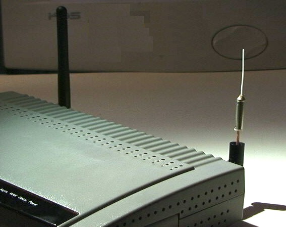
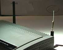 This is a D-Link DI-714 802.11b Wireless Router, DSL Firewall, and Bridge. It is fitted with two (removable) dipole antennas. The dipole in the foreground has had its protective black plastic cover removed, so that you can see its construction (magnified view here).
The dipole has a (white) radiating element just one inch long. This performs an equivalent function to the "rabbit ears" antennas on television sets. It is much smaller because the WLAN frequencies are in the 2,400-MHz microwave spectrum instead of the 100-MHz TV spectrum. As the frequency gets higher, the wavelength, and the antennas, become smaller.
I have used the Numerical Electromagnetic Code (NEC) Finite-Element Antenna Simulator software from the Lawrence Livermore Laboratories to calculate the theoretical radiation pattern of this dipole antenna. (A radiation pattern is a diagram that allows us to visualize in what directions the energy will radiate from an antenna.) The NEC software, which was originally written in Fortran, is available for Linux, Windows and MacOS.
You can see that the dipole radiant energy is concentrated into a region that looks like a donut, with the dipole vertically through the "hole" of the "donut." If an antenna radiates in all directions equally we say it is an "isotropic radiator." All practical antennas concentrate their energy into some region of the isotropic sphere.
I guess somebody should have designed a better way of visualizing 3-D radiation patterns, but it is often tough to get our minds around them. Consequently, we usually split the 3D donut (the red lines) into two perpendicular planes, called Azimuth and Elevation. We can then visualize these polar plots, rotate them conceptually in our mind, and allegedly form a 3D overview more easily. Azimuth and Elevation patterns are supplied for every commercial antenna, and once you have a grasp of how the polar plots combine (in your mind) to form the "red line" 3D pattern, it will become very easy to choose an antenna that is optimum for your application.
 |
When the RF energy is concentrated, such as into the yellow region of this cone, we say that the antenna has a "gain" over an isotropic radiator. The gain is measured in Decibels, a logarithmic measure. Gain over isotropic is written as "dBi." The isotropic gain is roughly equal to the inverse ratio of the areas of the yellow (coverage) region and the total surface area of the isotropic sphere. The gain of a dipole is roughly 2.1 dBi.
The dipole radiates equally in all directions around its axis (the Azimuth), but does not radiate along the length of the wire (above and below). Hence the donut pattern.
If a dipole antenna is placed in the center of a single floor of a multistory building, most of its energy will be radiated along the length of that floor, with some significant fraction sent to the floors above and below the access point.
We can reduce the amount of energy radiating to the floors above and below our target work area by squashing the donut. This type of antenna, termed a "Slotted Waveguide" or a "Co-linear," has a number of dipoles, one above the other, radiating their signals in phase so that the energy is concentrated along the axis of the dipole(s).
This is the (calculated) radiation pattern of a 6-dipole slotted waveguide antenna that I built. Its gain is 8.6 dBi. Every 6-dB increase in gain means that the range over which the signal propagates has been doubled over that of a single dipole. This gives a stronger signal for users within the main lobes of the radiation pattern. At the same time the sidelobe energy going above and below the main donut has been attenuated to 12 dBi, or 20 dB lower in strength than the main signal.
This means that the energy radiated to floors above and below our desired work area has been reduced just as if they were 10 times further away from the access point than our users. It has become many times harder for someone not in our primary coverage area to intercept our WLAN signal and compromise its security.
Directional Antennas
The dipole is an "omnidirectional" antenna, because it radiates its energy in all Azimuth directions equally. Directional antennas concentrate their energy into a cone, known as a "beam."
This is the radiation pattern of a Biquad. An antenna such as this could be placed in the corner of a work area, concentrating the energy into the work area and radiating very little outside the building (to the back and sides of the antenna).
The gain of this antenna is 11.3 dBi. I have only shown the Azimuth plot, as the elevation is essentially identical. Notice that all sidelobes are at least 20 dB lower in level, we normally say "20 dB down," from the main lobe signal strength. In general, it is much easier to get high gains from directional rather than from omnidirectional antennas.
Horizontal and Vertical Polarization
The dipole transmits a vertically polarized signal. This means that the electrical component of the energy, the so-called "E-field," is parallel to the dipole element and perpendicular to the floor. By turning the dipole 90 degrees (so its axis is horizontal) it will radiate a horizontally polarized signal, where the E-field vector is parallel to the ground.
In my experience, horizontally polarized antennas generally propagate better within a building, probably due to reflections from the floor and ceiling.
When the WLAN signal hits an object, such as a metal cabinet or pole, it is reflected, and its polarization is scattered. Inside any work area there will be a mixture of vertically and horizontally polarized signals.
PCMCIA Cards Have Terrible Inbuilt Antennas
And this leads us nicely into the real world. The designers of the antennas for PCMCIA cards face a real problem. It is not easy to form antennas onto the small circuit board inside the bulbous plastic cover that sticks of the end of the PCMCIA card. I won't go into the technology here, but below is plotted a typical sensitivity measurement for a laptop equipped with a PCMCIA WLAN card. The effective gain of this antenna is low, less than 0 dBi (typically -4 dBi) and it is very directional.
 You can see that the sensitivity varies greatly with Azimuth, and is quite unlike a well-behaved antenna. If you look at the blue trace you can see that the antenna is 6 dB more sensitive (twice the range) for signals coming in at 165 degrees compared with those at 330 degrees. There are also deep nulls, from which directions no signal at all is received.
The red trace shows sensitivity to vertically polarized signals. It is significantly lower than for horizontal polarization. I always recommend the use of horizontally polarized access point antennas when a significant number of PCMCIA-equipped workstations will be in use.
It should now be obvious why you have to jiggle and wiggle and rotate your laptop to get a decent WLAN signal. There has to be a better way...
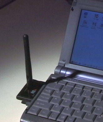
Zoom-Air 4105
Zoom-Air has a PCMCIA card it ships with a PCI adapter that contains a very handy SMA-RP socket for an external antenna. Here is a picture of it in my Vaio laptop. The card is equipped with a standard (crummy) antenna, but you have the option of merely screwing a dipole onto it if you are in a weak signal area. This is not an ideal solution, but it is much handier than having to carry around cables and other things that get lost in my laptop case. Another advantage — they do sell spare antennas to replace the ones you lose. Compex WLU-11
The Compex WLU- 11 is a self-contained USB WLAN client. It does not have any PCMCIA card internally (unlike most other USB clients). It has two easily removed shielding panels, below which are the pins ready to solder an SMA connector. This device offers one of the easiest ways to get a working 802.11b Prism-II reference test bed. The dipole antenna is easily desoldered, and this device is a WLAN hacker's paradise. Oh — it also is a very nice WLAN client for those of us who don't care to rip things apart.
Good Antennas and Bad Antennas
WLANs operate at a frequency of 2.4-2.4835 GHz. These are microwave frequencies, and many antennas that work well at lower frequencies are just not suitable for WLAN deployment. On the other hand, a 3-foot piece of 4x2 inch aluminum rectangular tube with a few slots cut in its sides makes a very high gain omnidirectional antenna.
Antennas for WLAN deployment must be chosen carefully. I tend to favor simple antennas. There is less that can go wrong. There are parabolic grid and reflector antennas from Hyperlink, Andrews/Conifer, Wincomm, and Telex.
In the omnidirectional antenna category there is a standout. Although very expensive, the Andrews Waveguide Omnidirectional offers high omnidirectional gain as well the horizontal polarization that will easily penetrate cubicle walls.
Most of the manufacturers listed above offer vertical polarization omnidirectionals, many at a much lower cost.Agere and Cisco offer fully integrated systems, ideal for less demanding deployments.
The SWR Specification
We have seen how the radiation patterns of an antenna are the most important factor to consider when choosing an antenna. There is one other important specification, the Standing Wave Ratio (SWR). This is a measure of the amount of energy absorbed and radiated by an antenna compared to the amount it reflects back to the transmitter. An SWR value of 1:1 is perfect (no reflected energy), while a WLAN antenna should have an SWR less than 1.5:1.
If its SWR is greater than 1.5 (1.5:1) over any region of the WLAN frequency range, do not buy it. In addition to signal attenuation, the reflected energy causes radiation from the coaxial cable and spurious sidelobes that can alert a sniffer.
This is a plot of energy reflected by my ultra-high-gain dish antenna as a function of frequency.
The graph above shows reflected energy from the 30-dBi gain parabolic dish I built as a reference antenna. The sweep frequency range is quite large, but the reflected energy between the two markers designating the 2.4-GHz WLAN band is essentially zero, with an SWR well under 1.25
The graph was produced with my HP 8690 Microwave Sweep Generator, a directional coupler, an HP 18-GHz RF detector and my HP 54522 Digital Scope. There is significant reflected energy at the 2402-MHz marker, indicating that the antenna is not performing well on WLAN Channel 1. In fact, ultra-high-gain antennas are not allowed to radiate on channels 1 and 2 or 10 and 11, and I have computer optimized the performance of the dish feed for channels 3 through 9. Throughout this range it has virtually no reflected energy, a unity SWR, and has sidelobes 40 dB down on its main beam.
That means that the sidelobes radiate less than 1/100th the distance of the main beam, confining almost the entire signal within the path to the target. The horizontal beamwidth is about 3 degrees.
Be fussy when buying antennas. If you shop around, it is possible to find systems that generate very little spurious energy. Insist on getting a full set of specifications and polar plots so that you can properly evaluate them.
FCC Radiated Power Rules
The FCC foresaw that unlicensed 802.11b WLANs would be used to link networks at distances of several miles (although I am sure they had no idea of the ultimate potential of the open networks that are springing up). Because 802.11b uses the 2.4-GHz ISM band, transmitters and receivers have to coexist with each other, accepting interference from Microwave Ovens and Portable Telephones in addition to interference from other wireless LANs.
On balance, they decided to encourage the use of high-gain antennas for point-to-point communication, as high-gain directional antennas have tightly controlled beams that do not spray radiation over such a large area.
The FCC had already decided to place a limit of +36 dBm (4 watts) Effective Isotropic Radiated Power (EIRP) on Multi-Point WLAN links, and a maximum power of +30 dBm (1 watt) at the WLAN tranmitter's connector. So they also defined that if any antenna used in point-to- point links has a gain higher than 6 dBi, the transmitter power must be reduced so that the "peak output power of the intentional radiator" is reduced by 1 dB for every 3 dB of antenna gain beyond 6 dBi.
This is a gift from the FCC. It allows point-to-point WLANs to achieve an EIRP well in excess of +36 dBm, and the greater range that results from the higher power. Here is a table of some typical values:
| Antenna Gain | Max Antenna Input Power | Attenuation | EIRP(max) |
| +6 dBi | +30 dBm | 0 dB | 36 dBm |
| +12 dBi | +28 dBm | 2 dB | 40 dBm |
| +18 dBi | +26 dBm | 4 dB | 44 dBm |
| +24 dBi | +24 dBm | 6 dB | 48 dBm |
| +30 dBi | +22 dBm | 8 dB | 52 dBm |
The output of unamplified Orinoco or Prism WLAN chipsets is less than +22 dBm, typically about +18 dBm, or 60 milliwatts. If you do not have an external power amplifier, or a higher power access point, you can employ an antenna with up to 30 dBi of gain without fear of retribution from the FCC. With a higher power transmitter you will need to add coaxial attenuators (remember that the loss in your coaxial cable can be included in this attenuation requirement).
Coaxial Cable
As you can see from the size of the dipole antenna, just one inch of wire becomes an antenna at these microwave frequencies, and it is critical that you use high-quality coaxial cable, with SMA, TNC, or N series connectors. Thin coax, of the one-eighth-inch RG-174 variety, has an attenuation (loss) of about 3 dB for every 4 feet of its length. You lose half your signal in every 4 feet of cable. It is not a very good idea to use this stuff at WLAN frequencies.
I personally use Times Microwave LMR-195 coax for short runs (2-3 feet). It uses the same SMA and N connectors as RG-58. For longer runs I use LMR-400, similar in size to RG-8, which has a loss of 3 dB for every 40 feet of cable length. Small quantities of these cables and connectors can often be found on eBay.
Diversity
Most access points have two antennas. One of these is used as the primary transmitting and receiving port, while the other is periodically checked (polled) to see if it is receiving a stronger signal than the main antenna. This is called a "diversity" antenna system. It can help to reduce variations in signal strength as you vary the location of an access point and a client. While there is nothing to stop you deploying two good antennas for each access point, one good antenna is always superior to two ordinary ones.
Attenuators
Now that you have increased the signal strength in your work area way beyond the needs of your users, the next step in security enhancement is to attenuate the output from your access point. Attenuation of the signal in your workspace will also attenuate the signal that leaks to the outside world.
Fixed coaxial attenuators are available in a variety of sizes and configurations. I suggest that you start with 3 dB attenuators, and cascade them until you start to lose coverage within your workgroup.
Summary: Isn't It Fun?
I have always loved RF technology. As a kid, I have fond memories of playing with surplus radio gear, and I built my first transmitter before my first TV set, and long before my first computer. Ah — those were the days...
Now, with the ready availability of numerical modeling, it is easy to produce complex RF filters using PCB microstrips, and to design antennas that you actually expect to work! This is a far cry from the "cut-and-try" techniques of the past. And the technology is not standing still. NEC was written in Fortran, for input from card decks on (slow) mainframes. I was surprised to find that the 4000-element NEC program that I am using on my PC is many times more capable than the simulators used by the scientists at Lawrence Livermore only a decade ago.
The tools may change, but the fundamental rules of electromagnetic propagation and antenna theory do not. Put a signal in the air and chances are that somebody will hear it. Our ancestors never dreamed of desktop computers, let alone computers connected together through the ether.
Wireless networking is an amazingly complex technology. Deployment of a good WLAN need not be difficult, but it does require care and planning. RF technology often seems esoteric, but nothing beats the feeling of successfully sending a radio signal through that ether...
Acknowledgments
A lot of people contributed to the preparation of this tutorial, particularly David Jefferies, Paul Wade (W1GHZ), John Richey (Agere Systems), and Darrel Emerson. Without their input it would have been a lot shorter.
Trevor Marshall is an engineering management consultant, with interests ranging from RF and Hardware design to Linux internals, Internet infrastructure, MPEG, and Digital Video. He started his career in the '70s, designing the Maplin Electronic Music Synthesizers. When the Microcomputer came along, he got sidetracked into computer software, programming the 2650, 8080, Z80, Z8000, 8048, 8306, 6805, 80x86, and Power PC families. Along the way, he also picked up a little expertise in RF system design, biomedical engineering, and the printing industry. His web site is www.trevormarshall.com.
